
The input resistance is the opposition offered by the base-emitter junction to the signal flow.īy definition, it is the ratio of small change in base-emitter voltage (ΔV BE) to the resulting change in base current (ΔI B) at constant collector-emitter voltage. Input ResistanceĪs the input circuit is forward biased, the input resistance will be low. Performance of AmplifierĪs the common emitter mode of connection is mostly adopted, let us first understand a few important terms with reference to this mode of connection. Hence it is observed that a change of 0.1v in the input gives a change of 5v in the output, which means the voltage level of the signal is amplified.
#Biasing transistor amplifier install#
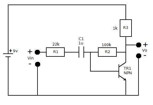
Install 100 ohm resistor (brown-black-brown-gold/silver) between collector and the (+) of the battery. This emitter current will obviously produce a change in collector current, which would also be 1mA.Ī load resistance of 5kΩ placed in the collector would produce a voltage of Connect the (-) pin of the battery to the emitter lead of the transistor. Let there be a change of 0.1v in the input voltage being applied, which further produces a change of 1mA in the emitter current. Thus a small input voltage results in a large output voltage, which shows that the transistor works as an amplifier. The emitter current caused by the input signal contributes the collector current, which when flows through the load resistor R L, results in a large voltage drop across it. The low resistance in input circuit, lets any small change in input signal to result in an appreciable change in the output. The below figure shows how a transistor looks like when connected as an amplifier. This forward bias is maintained regardless of the polarity of the signal. The DC bias voltage applied to the emitter base junction, makes it remain in forward biased condition. Transistor AmplifierĪ transistor acts as an amplifier by raising the strength of a weak signal. Since the diode is smaller it also has slightly higher internal resistance such that it's current and thus PN voltages are controlled by the equal R1,R2 drops into the total supply voltage remaining. Here, let us focus how a transistor works as an amplifier. Then the Class AB uses the input diode pair to control the output Vbe pair which controls the output DC current. We will discuss the need for proper biasing in the next chapter. Emitter Follower & Darlington Amplifierįor a transistor to act as an amplifier, it should be properly biased.


 0 kommentar(er)
